OpenPlant Orthographics Manager Help

Execution/Filters

The options displayed in this page define the priority of the input information when it is processed, and also helps to determine how the information is arranged on the output drawing(s).

Define the properties per the fields described below and Save the changes.

The Close icon closes the Project Settings interface, so make sure your changes are saved. You will be prompted to save them it you haven't already.

The Load Defaults icon in the main Settings interface will return the settings of the options page to their original values.
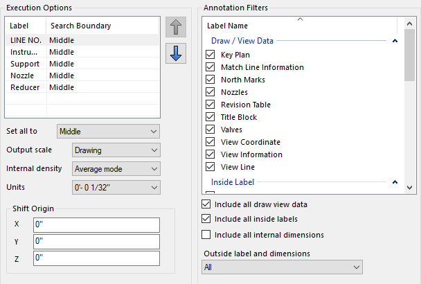
Execution Options

SettingDescription
Labeling Priority
There are 5 types of design components which require inside labels inside of Orthographics Manager:
  • Line No.
  • Instrument
  • Support
  • Nozzle
  • Reducer

The priority of the label placement is determined by the placement in the label list at the top left section of the page. To change the priority of a label, select the label in the grid and use the Up/Down icons to re-position the label in the list.

Note: Generally, the label having the longest text and biggest enclosure gets placed first.
Note: Once the label is placed in an area according to the priority order, its area will be reserved. This means that other labels will not be placed in this reserved area to avoid the interference with others.

See the labeling priority examples below:

OPOM searches free space to locate Line No. first

OPOM searches free space to locate Instrument first.

Search Boundary
The Search Boundary is based on the tag origin point for the internal labeled items. They can be set for each label item by selecting it from the drop down list in the Search Boundary field. Three options are available:
  • Fast: This search area is the smallest. It allows you to place inside view labels the shortest distance possible from the tag origin point. If Orthographics Manager finds the proper space to place the label within the searching area without interference, it will be selected. However, it may be overlapped with other labels if there are a lot of graphical elements with tagging items which exist around the tag origin point.
  • Middle (Recommend): The search area is extended from the Fast mode. If no space is found without interfering with another label in the limited searching boundary, the label string and enclosure shape will be placed with minimum interference (overlapping). With this option, the priorities between the shortest distance from the tag origin and no interference with others will be balanced properly.
  • Detail: The largest search area option. With this option, the label with enclosure symbol may go further than the Middle mode option, if there is not enough blank space to place the label. By this option, the label that does not interfere with others takes precedence over the label that has shortest distance from the tag origin point.
Set all to Sets a default Search Boundary to apply to all label types. Pick from the following:
  • Fast
  • Middle
  • Detail
Output Scale

Select from the following options:

  • Drawing: When Orthographics Manager generates the output drawing, it reduces the model according to the view scale defined for the 2D View Volume. (See the Create View page for details on this.)For example, if the scale is set to 1/50 (or 1mm = 50mm), then for an output dimension of 2000 mm in the drawing such as shown below, the true distance = 40mm.
    Note: When using the Drawing scale method, the scale does not apply to predefined size values for annotation labels. These values already take the drawing scale into consideration.
  • Model: The output drawing is drawn using the real dimensional values and not scaled down. The annotation height values in this case are multiples of the defined scale value.
    For instance, if the annotation height is set to 2.5mm as shown below:

    then the height value is multiplied by the view scale (using the 1/50mm example above)

    5mm x 50mm = 125mm

    This is reflected in the Element Info dialog when you select an annotation label in the drawing:
Internal Density

The following options are available:

  • Sparse Mode: Orthographics Manager finds the blank space to place labels by the interval of sparse step. You can save the runtime by this option. However, it may not be made sophisticated placement of labels.
  • Average Mode: The default option, the average mode allows you properly balanced option between the runtime and elaboration of the drawing.
  • Dense Mode: Orthographics Manager finds the blank space to place labels by the interval of dense step.
    Note: This option can be time consuming, especially with a big searching boundary.
Units Orthographics Manager supports both metric and inch-feet unit types. Select the desired output unit type from the list to apply to the View Coordinates, Tag Numbers and Equipment Coordinates.
Shift Origin Enter coordinate values into the fields to shift the origin point of the view in the resulting drawing file .

Annotation Filters

This section of the Options page lets you toggle the display the different items that are displayed on a GA drawing. The items are grouped as follows:

SettingDescription
Label Name
The Labels are broken into the following three categories, which are collapsible as shown in the following figure. Enable/Disable the checkbox next to each item to determine whether it will be displayed in the final output drawing.
Draw/View Data
  • Key Plan
  • Match Line Information
  • North Marks
  • Nozzle Chart
  • Revision Chart
  • Title Block
  • Valve Chart
  • View Coordinate
  • View Information
  • View Line
Inside Label
  • Beam
  • Cable Tray
  • Flow Marks
  • HVAC Components
  • Instrument
  • Line Number
  • Nozzle
  • Pipeline Hatch Marks
  • Reducer
  • Slope Marks
  • Special Items
  • Support
  • Valve Number
Internal Dimension Items
  • Beam
  • Column Center
  • Equipment Center
  • HVAC Components
  • Instrument
  • Pipe
  • Support
  • Valve Number
Include all draw view data Enabled: All of the Draw/View Data items are checked for placement in the output drawing.

Disabled: When you disable this option it unchecks all of the Draw/View Data items so they will not be placed in the output drawing.

Note: This option is for selecting/deselecting ALL of the items. You can also manually toggle the individual items as explained above.
Include all inside labels Enabled: All of the Inside Label items are checked for placement in the output drawing.

Disabled: When you disable this option it unchecks all of the Inside Label items so they will not be placed in the output drawing.

Note: This option is for selecting/deselecting ALL of the items. You can also manually toggle the individual items as explained above.
Include all internal dimensions Enabled: All of the Internal Dimension Items are checked for placement in the output drawing.

Disabled: When you disable this option it unchecks all of the Inside Label items so they will not be placed in the output drawing.

Note: This option is for selecting/deselecting ALL of the items. You can also manually toggle the individual items as explained above.
Outside label and dimensions
Select one of the options from the list which controls the type(s) of Outside dimensions that will be displayed:
  • All
  • Pipe, HVAC and Cable Tray
  • Pipe, HVAC, Cable Tray and Equipment
  • Pipe, HVAC, Cable Tray and Structural Grid
  • Global Dimension
  • None